


Before we start writing code, we need to go over some of the basics concept and algorithms used in 3D programming. Essentially, we need to make sure we're all speaking the same language. In this chapter, we're going to discuss some of the most basic and fundamental concepts underlying the use of OpenGL ES 2.0, as well as some of the data structures and algorithms that we'll need to create and manipulate virtual three-dimensional objects. We'll talk about what vertices, vectors, polygons, and colors are and how they are represented in OpenGL ES.
We'll also look at some of the math that you'll need to perform on each of them. The math involved in computer graphics can be mind-numbingly complex at times, but don't worry, we're going to ease into the math slowly. I know it's a little bit of a challenge to dive into the math before we even create our first program, but what we're talking about in this chapter are the building blocks that will form the foundation of everything else we create. For many of you, much of this chapter will be a review of some pretty basic geometry, trigonometry, and linear algebra concepts you may have learned in college or high school, but don't get scared off if it's all completely new to you.
The Cartesian coordinate system defines an arbitrary point called the origin. This point is where the value of X, Y, and Z are all 0.0. Each of the three axes are like rulers with imaginary, evenly spaced numbers on them. If, for example, one object is to the right of another object, we assign it a higher X value than the other object. If it is above the other object, it has a higher Y value. By referencing the origin, any point in space can be described using a sequence of three numbers. A point where X is equal to +3, Y is equal to +1, and Z is equal to -1 is a little to the right, above, and behind the origin.

The Cartesian Coordinate System
When programming in OpenGL ES, the location of a single vertex is typically represented as an array of variables with a length of three: one to represent the X value, one to represent the Y value, and one to represent the Z value. Most often, we use an array of GLfloats for this purpose, but it doesn't have to be; OpenGL ES allows you to select the datatype you want by selecting the appropriate “alphabet soup” version of functions. Because of the design of the GPUs currently used on iOS devices, GLfloat is generally the best choice.
To allocate memory for a single vertex and assign its location value, you might do something like this:
The order of the values we use here is important. OpenGL ES always expects the vertex data to be submitted in a specific order: first X, then Y, and then Z.
More often than not, you'll be working with more than one vertex. You can't make very interesting models out of a single vertex. In fact, you're pretty much limited to making a dot. Take my word for it, being limited to drawing a dot isn't all that much fun. When you have to submit multiple vertices to OpenGL ES at the same time, OpenGL ES expects you to provide an array that's large enough to hold the data for all of the vertices. It also expects to receive the data in a specific order: first the X, Y, and Z value of the first vertex, then the X, Y, and Z value of the next vertex, and so on. For example, to allocate enough space for 9 vertices (which requires a total of 27 values) and assign values to them you might do something like this:
Once your data model consists of more than a handful of vertices, your code can get pretty unwieldy. Fortunately, most of the time your vertex data will come from external files generated by a 3D modeling program, rather than being done with long sequences of variable assignments like I'm showing here, but even so, trying to remember which axis and vertex a particular index in an array corresponds to is a pain. Quickly, now, what's the index for the Z axis of the 7th vertex? I know, right? More math! Sheesh.
We can save ourselves some grief and make our code much more readable by defining a struct to represent a single vertex like this:
A Vertex3D represents a single point in space. As far as what happens when you compile your code, allocating a single Vertex3D is exactly the same as allocating an array of three GLfloats, but now our code becomes easier to read:
This code is exactly the same as the earlier code as far as the compiler is concerned, but this code is much more readable. If we want to assign something to the Z axis of the seventh vertex, we just do this:²
Of course, in real programs, often the vertex data you'll be using will be too big to create effectively on the stack and will come, instead, from data files created in 3D modeling packages. Fortunately, creating space for vertices on the heap is just about as easy:
As you can see from the code sample, we can use vertices allocated on the heap just like we did earlier with the array of vertices allocated on the stack, thanks to the C language's pointer and array equivalency. The only difference between vertices on the heap and on the stack is that with heap allocated vertices, you need to remember to free your memory when you're done with it. We'll talk more about strategies for managing memory later in the book. For the first several exercises, we'll be using small numbers of vertices and will just be allocating them on the stack.
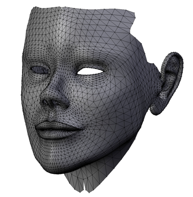
Even very complex shapes can be created using nothing but triangles
There are a few more things you need to know about triangles, however. In OpenGL ES, there is a concept known as winding, which just means the order in which the vertices are drawn matters. Unlike objects in the real world, polygons in OpenGL do not generally have two sides to them. They have one side, which is considered the frontface and, by default, a triangle can only be seen if its frontface if facing the viewer. While it is possible to configure OpenGL to treat polygons as two-sided, by default, triangles have only one visible side. By knowing which is the front or visible side of the polygon, OpenGL is able to do half the amount of calculations per polygon that it would have to do if both sides were treated as visible.
Although there are times when a polygon will stand on its own, and you might very well want the back side drawn, usually a triangle is part of a larger object, and one side of the polygon will be facing the inside of the object and thus will never be seen. The side that isn't drawn is called a backface, and OpenGL determines which is the front face to be drawn and which is the backface by looking at the drawing order of the vertices, which is the order they are submitted to OpenGL ES. By default, the front face is the one that would be drawn by following the vertices in counter-clockwise order. Since OpenGL can determine easily which triangles are visible to the user, it can use a process called backface culling to avoid doing work for polygons that aren't facing the viewer and, therefore, can't be seen.
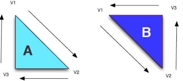
The Winding Rule
In the illustration above, the lighter triangle on the left marked “A” is a backface and won't be drawn because the order that the vertices would be drawn in relation to the viewer is clockwise. On the other hand, the darker triangle on the right labeled “B” is a frontface that will be drawn because the order of the vertices is counter-clockwise in relation to the viewer.
Here's the funny thing about vectors: they look almost exactly like vertices. They contain three values, one for each Cartesian axis. In code, they looks like this:
Yeah, that looks pretty much exactly like the Vector3D struct we created a moment ago, doesn't it? In fact, we could actually just use the same struct for both, by doing this:
So, what's going on here? Why do we have two different things that look exactly the same? How can a single point in space represent a direction and a distance? Well, a vector actually has two points in space. The one represented by the X, Y, and Z values, and the origin. Think of a vector as an imaginary line or arrow drawn from the origin to a specific point in space. The further a point is from the origin, the greater the velocity or distance it represents. With vectors, the distance from the origin to the stored position is known as the vector's magnitude.
Because the Vertex3D and Vector3D structures are exactly the same, a lot of 3D libraries and code do not bother defining two distinct datatypes. They just use the term “vector” generically to represent both vertices and vectors, or even more generically to refer to short sequences of floating point numbers. In fact, GLSL, the programming language used to write shaders (which we'll start looking at in the next chapter), does exactly that. It uses “vector” datatypes to represent pretty much anything that's a sequence (or one-dimensional array) of floating point values, such as vertices, vectors, and even colors. In our C and Objective-C code, however, we're going to separate out vertices and vectors to help reinforce the fact that there are two different (albeit related) concepts at play here.
We obviously don't have time to cover all of trigonometry before getting started, but it's worth taking a second just to remind you what the three most basic trigonometric functions represent, since we'll be using them quite a bit throughout the book and, in many cases, understanding that is the lynchpin in understanding why something works.
Given any angle, you can construct an imaginary right-triangle. Given a particular angle (the one marked ϴ (theta) in the next figure, we can take the two lines that make up the angle and add a third imaginary line that connects the other two and form a right angle (90° angle) with one of the other two sides. As long as we have two vectors with a common starting point, we can add a third line to get a right triangle. The side of this triangle that is opposite the angle we're discussing is called, imaginatively, the opposite. The side of the triangle that is at a 90° angle with the opposite is called the adjacent. The remaining side, which is always the longest side of a right triangle, is called the hypotenuse.
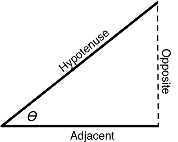
The Terminology of the Basic Trigonometric Functions
Now that we have some common terminology, let's look at the three basic functions:
When we use one of these operations in our code, I'll try to point out why we're using it, but it's not a bad idea to do a basic review of trigonometry if you're at all rusty. One important thing to remember about the C functions for sine, cosine, and tangent is that they expect and return angles represented as radians, not as degrees. Fortunately, it's relatively trivial to convert back and forth between radians and degrees by adding the following two macros to your code:
Once you have these macros, you can convert back and forth with ease. To convert a 45° angle to radians and then back to degrees, we can do this:
and see how I've drawn a triangle so that the line between the two vertices is the hypotenuse.
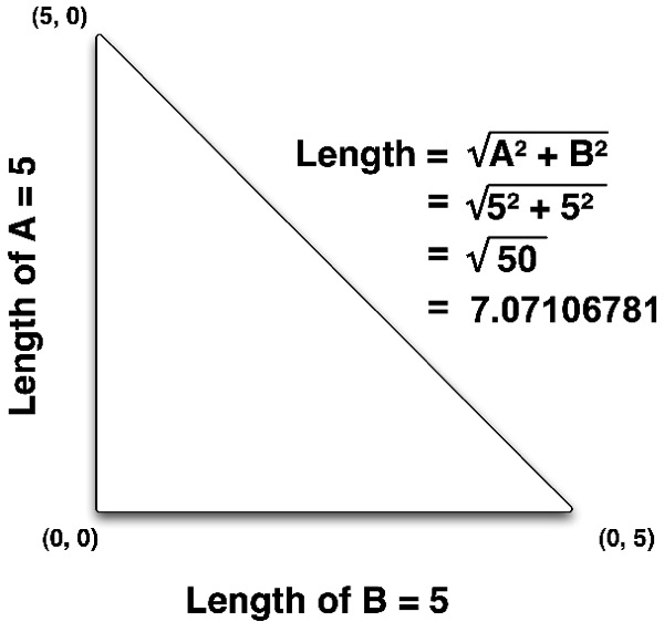
The Pythagorean Formula used to calculate distance between two-dimensional vertices
Since I've drawn a right triangle, the length of the other two sides of the triangle are pretty easy to calculate because it's basically the difference between the two vertices. If we subtract the X value of one vertex from the X value of the other vertex, that gives us one of the other two sides. If we do the same thing with the Y value, we get the distance of the other side and then we can calculate the hypotenuse using the Pythagorean Formula. In high school math, we learn that the Pythagorean Formula isA + B = C , so the distance of the hypotenuse can be calculated by squaring the other two sides, adding them together, and calculating the square root of the sum.
It turns out, however, that the calculation derived from Pythagoras's formula doesn't apply to just two dimensions: it works equally well when applied to three dimensions, or even when applied to larger coordinate systems. To calculate the distance between two three-dimensional vertices, we just calculate the difference between the X values and square it, then do the same with the Y and Z values, add them all together, and take the square root of the total.
Here's what it looks like in code:
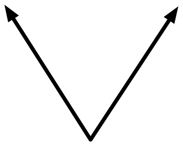
Drawing two lines to represent two vectors
The origin of the name “cross product” is similar to that of the dot product. The same mathematician who discovered the dot product discovered the cross product calculation, and he used a cross symbol (×) to denote the operation in his writings, and the operation soon came to be known as the “cross product.”
Here's how you calculate the cross product of a vector:
Normalizing a Vector
For some purposes that vectors are used in graphics programming, the magnitude doesn't really matter. In some instances, the only information that's needed is the direction of the vector. In these situations, it's pretty common to do something called normalizing the vector. When you normalize a vector, you change its magnitude to 1.0 without changing the direction the vector points. The result of normalizing a vector is referred to as a unit vector or sometimes a normalized vector. The reason for normalizing vectors when the magnitude isn't used is that many calculations are shorter and faster when performed on unit vectors. In fact, normalizing one or more vectors is a step in many of the algorithms we'll use. If we normalize the vector once and store it that way, every subsequent operation performed can avoid normalizing it unless its value changes, since it's already been normalized.
Normalizing a vector is accomplished by dividing each of the three components (X, Y, Z) by the magnitude of the vector. The only gotcha is to make sure you don't divide by zero. Here's how you calculate it:
Very often, when you need to subtract vectors, you'll want the result to be expressed as a unit vector. Here's another function to calculate a unit vector based on two vertices, which leverages the previous function, then normalizes the result:
To specify color, you can call an OpenGL ES function designed for that purpose and pass the four component values that make up the color you want to set. For example, to set the current drawing color, you would call glColor4f() and pass in the four components. To set the current color to an opaque red, for example, you would do this:
This technique is somewhat limiting, as you'll see in the next chapter, because everything that gets drawn — until the next time glColor4f() is called — will get drawn in red. To do anything sophisticated with colors, you'll need the ability to specify colors on a per-vertex basis. When you do that, OpenGL ES expects the color data to be specified the same way as with vertices: using an array of variables. As with vertices, the order that you specify the values matters. OpenGL ES expects colors to be specified with four elements and expects those elements to be provided in the order: red, green, blue, then alpha, like so:
Just like with vertices, dealing with large arrays of color components can get tedious. Fortunately, we can make our code more readable the same way we did with vertices, by defining a new datatype to represent a single color:
Before we can start coding, though, we need to look at the architecture and basic use of OpenGL ES 2.0's programmable pipeline so that we know where to put our code.
1 - This coordinate system, which is called “y up” for obvious reasons, is the most commonly used and it's the one we'll use use with OpenGL ES. There is, however, an alternate coordinate system where the Z and Y axis are swapped called, the “z up” coordinate system. In this coordinate system, the Z axis moves up and down and the Y axis moves towards and away from the viewer. This alternate coordinate system is used in many CAD software packages, as well as a small number of other 3D software packages, most notably the open source program called Blender. You can convert from the Z up coordinate system to the Y up coordinate systems by simply rotating objects 90° on the X axis.
2 - I probably don't need to tell you this, but just in case you're confused, remember that C is a zero-indexed language, so the seventh vertex has an index value of 6.
3 - Okay, there are actually six trigonometric functions — plus each one has an inverse or quasi-inverse functions — but these three are the most basic and are the ones most often used in 3D programming.
We'll also look at some of the math that you'll need to perform on each of them. The math involved in computer graphics can be mind-numbingly complex at times, but don't worry, we're going to ease into the math slowly. I know it's a little bit of a challenge to dive into the math before we even create our first program, but what we're talking about in this chapter are the building blocks that will form the foundation of everything else we create. For many of you, much of this chapter will be a review of some pretty basic geometry, trigonometry, and linear algebra concepts you may have learned in college or high school, but don't get scared off if it's all completely new to you.
The Cartesian Coordinate System
The first thing you need to understand before doing any 3D graphics programming is how locations are represented in a three-dimensional world. In order to describe the position of any particular point in space, we use three imaginary lines that we call axes that are typically named X, Y, and Z. The X axis is an imaginary line that runs from left to right from the perspective of the viewer, the Y axis is an imaginary line that runs up and down, and the Z axis is an imaginary line that extends towards the viewer and away from him or her.¹OpenGL ES Units
One of the questions that may pop to mind when we talk about Cartesian coordinates is, "What units are we talking about here?" When we say that Y equals 1.383, what does that mean? It's 1.383 units from the origin, but what are those units?
Well, they're OpenGL units. They're completely arbitrary. When you design your program, you get to decide what they represent. Each unit could be a meter, a foot, and inch, or a fathom, whichever your application needs.
The Cartesian coordinate system defines an arbitrary point called the origin. This point is where the value of X, Y, and Z are all 0.0. Each of the three axes are like rulers with imaginary, evenly spaced numbers on them. If, for example, one object is to the right of another object, we assign it a higher X value than the other object. If it is above the other object, it has a higher Y value. By referencing the origin, any point in space can be described using a sequence of three numbers. A point where X is equal to +3, Y is equal to +1, and Z is equal to -1 is a little to the right, above, and behind the origin.
Vertices
In order to define objects in a virtual 3D world, we use the three axes to define points in space and then connect them. To draw a triangle, for example, we would define three points in space, which means three X, three Y, and three Z values; the X, Y, and Z values have to be grouped together so we know which X goes with which Y and which Z. We call this grouping of a single X, Y, and Z value a vertex. A vertex represents a single point in space, and it is the atomic unit of three-dimensional graphics.When programming in OpenGL ES, the location of a single vertex is typically represented as an array of variables with a length of three: one to represent the X value, one to represent the Y value, and one to represent the Z value. Most often, we use an array of GLfloats for this purpose, but it doesn't have to be; OpenGL ES allows you to select the datatype you want by selecting the appropriate “alphabet soup” version of functions. Because of the design of the GPUs currently used on iOS devices, GLfloat is generally the best choice.
To allocate memory for a single vertex and assign its location value, you might do something like this:
GLfloat vertex[3];
vertex[0] =  12.234f; // X axis value
vertex[1] = -1.253f;  // Y axis value
vertex[2] =  0.512f;  // Z axis value
The order of the values we use here is important. OpenGL ES always expects the vertex data to be submitted in a specific order: first X, then Y, and then Z.
More often than not, you'll be working with more than one vertex. You can't make very interesting models out of a single vertex. In fact, you're pretty much limited to making a dot. Take my word for it, being limited to drawing a dot isn't all that much fun. When you have to submit multiple vertices to OpenGL ES at the same time, OpenGL ES expects you to provide an array that's large enough to hold the data for all of the vertices. It also expects to receive the data in a specific order: first the X, Y, and Z value of the first vertex, then the X, Y, and Z value of the next vertex, and so on. For example, to allocate enough space for 9 vertices (which requires a total of 27 values) and assign values to them you might do something like this:
GLfloat vertices[27];
vertex[0] =  12.234f; // X axis for first vertex
vertex[1] = -1.253f;  // Y axis for first vertex
vertex[2] =  0.512f;  // Z axis for first vertex
vertex[3] = -3.359f;  // X axis for second vertex
vertex[4] =  52.03f;  // Y axis for second vertex
vertex[5] = -18.23f;  // Z axis for second vertex
// ... etc.
Once your data model consists of more than a handful of vertices, your code can get pretty unwieldy. Fortunately, most of the time your vertex data will come from external files generated by a 3D modeling program, rather than being done with long sequences of variable assignments like I'm showing here, but even so, trying to remember which axis and vertex a particular index in an array corresponds to is a pain. Quickly, now, what's the index for the Z axis of the 7th vertex? I know, right? More math! Sheesh.
We can save ourselves some grief and make our code much more readable by defining a struct to represent a single vertex like this:
typedef struct
{
    GLfloat x;
    GLfloat y;
    GLfloat z;
} Vertex3D;
A Vertex3D represents a single point in space. As far as what happens when you compile your code, allocating a single Vertex3D is exactly the same as allocating an array of three GLfloats, but now our code becomes easier to read:
Vertex3D vertex;
vertex.x =  12.234f;
vertex.y = -1.253f;
vertex.z =  0.512f;
Wait… struct?
As you almost certainly know, the iOS SDK uses the Objective-C language, which is an object-oriented superset of the C language. So, you may be wondering why we've used an old-fashioned struct rather than defining an Objective-C object to represent vertices.
The answer is quite simply one of performance. Today's iPhones are capable of drawing objects comprised of hundreds of thousands or even millions of vertices every second. There are a couple of issues here. First, OpenGL ES is not an object-oriented library, and it expects to be given data in C arrays using raw datatypes. That means if we used objects to store each vertex, we'd have to be constantly unboxing the data from our objects into C arrays to hand the data off to OpenGL ES, which would incur processing overhead and slow our program down.
Additionally, there is extra overhead associated with Objective-C objects both in terms of memory allocation and message dispatching. This overhead is inconsequential in most parts of most applications, but when you're moving around hundreds of thousands of these things every second, that overhead can become non-trivial. As a result, it makes sense to store low-level data like vertices using native C data structures. We'll use Objective-C objects later in the book for higher level objects, of which we won't have quite so many.
This code is exactly the same as the earlier code as far as the compiler is concerned, but this code is much more readable. If we want to assign something to the Z axis of the seventh vertex, we just do this:²
Vertex3D vertices[9];
vertex[6].z = newValue;
Of course, in real programs, often the vertex data you'll be using will be too big to create effectively on the stack and will come, instead, from data files created in 3D modeling packages. Fortunately, creating space for vertices on the heap is just about as easy:
Vertex3D *vertices = malloc(9 * sizeof(GLfloat));
vertices[0].x =  12.234f
vertices[0].y = -1.253f;
vertices[0].z =  0.512f;
As you can see from the code sample, we can use vertices allocated on the heap just like we did earlier with the array of vertices allocated on the stack, thanks to the C language's pointer and array equivalency. The only difference between vertices on the heap and on the stack is that with heap allocated vertices, you need to remember to free your memory when you're done with it. We'll talk more about strategies for managing memory later in the book. For the first several exercises, we'll be using small numbers of vertices and will just be allocating them on the stack.
Assembling Vertices: Polygons
Multiple vertices can be used to represent lots of little dots, such as stars or raindrops. But the real power of vertices is when you start putting them together to create shapes and solid objects. When you pass a bunch of vertices into OpenGL ES, you specify how it should draw them, a process we'll look at starting in the next chapter. The next building block up from the humble vertex is the polygon. As you probably remember from high school geometry, polygons are enclosed shapes that rest on a plane. The simplest polygon, and the only one that OpenGL ES allows us to use is the triangle, which, of course, has three sides. Having to use only triangles might sound like a bit of a limitation, but it's really not. Any polygon can be divided up into triangles and even very complex shapes can be represented using nothing but triangles. Also, the hardware inside the iPhone is very, very good and very fast at drawing triangles.There are a few more things you need to know about triangles, however. In OpenGL ES, there is a concept known as winding, which just means the order in which the vertices are drawn matters. Unlike objects in the real world, polygons in OpenGL do not generally have two sides to them. They have one side, which is considered the frontface and, by default, a triangle can only be seen if its frontface if facing the viewer. While it is possible to configure OpenGL to treat polygons as two-sided, by default, triangles have only one visible side. By knowing which is the front or visible side of the polygon, OpenGL is able to do half the amount of calculations per polygon that it would have to do if both sides were treated as visible.
Although there are times when a polygon will stand on its own, and you might very well want the back side drawn, usually a triangle is part of a larger object, and one side of the polygon will be facing the inside of the object and thus will never be seen. The side that isn't drawn is called a backface, and OpenGL determines which is the front face to be drawn and which is the backface by looking at the drawing order of the vertices, which is the order they are submitted to OpenGL ES. By default, the front face is the one that would be drawn by following the vertices in counter-clockwise order. Since OpenGL can determine easily which triangles are visible to the user, it can use a process called backface culling to avoid doing work for polygons that aren't facing the viewer and, therefore, can't be seen.
In the illustration above, the lighter triangle on the left marked “A” is a backface and won't be drawn because the order that the vertices would be drawn in relation to the viewer is clockwise. On the other hand, the darker triangle on the right labeled “B” is a frontface that will be drawn because the order of the vertices is counter-clockwise in relation to the viewer.
Vectors
There's another piece of data that we'll be using a lot in 3D programming called a Euclidian vector, usually referred to as just a vector. A vector can represent both a direction and also a distance. Point your finger and extend your arm all the way so that you're pointing at something around you and your arm is straight. Your arm and finger are pretty much serving as a vector right now. One way vectors are used in 3D programming is when defining a directional light, like a spotlight. To define the direction that the light is pointing, we use a vector. If you were a virtual light, your finger might be the vector identifying what you were shining on.Here's the funny thing about vectors: they look almost exactly like vertices. They contain three values, one for each Cartesian axis. In code, they looks like this:
typedef struct
{
    GLfloat x;
    GLfloat y;
    GLfloat z;
} Vector3D;
Yeah, that looks pretty much exactly like the Vector3D struct we created a moment ago, doesn't it? In fact, we could actually just use the same struct for both, by doing this:
typedef Vertex3D Vector3D;
Vector Components
A little later in the book, you'll see that vectors can have a fourth component called w. However, we'll rarely need to use the w value in our application code; it usually comes into play in code that runs in our shaders, so the datatypes we define here don't need the value.
A little later in the book, you'll see that vectors can have a fourth component called w. However, we'll rarely need to use the w value in our application code; it usually comes into play in code that runs in our shaders, so the datatypes we define here don't need the value.
So, what's going on here? Why do we have two different things that look exactly the same? How can a single point in space represent a direction and a distance? Well, a vector actually has two points in space. The one represented by the X, Y, and Z values, and the origin. Think of a vector as an imaginary line or arrow drawn from the origin to a specific point in space. The further a point is from the origin, the greater the velocity or distance it represents. With vectors, the distance from the origin to the stored position is known as the vector's magnitude.
Because the Vertex3D and Vector3D structures are exactly the same, a lot of 3D libraries and code do not bother defining two distinct datatypes. They just use the term “vector” generically to represent both vertices and vectors, or even more generically to refer to short sequences of floating point numbers. In fact, GLSL, the programming language used to write shaders (which we'll start looking at in the next chapter), does exactly that. It uses “vector” datatypes to represent pretty much anything that's a sequence (or one-dimensional array) of floating point values, such as vertices, vectors, and even colors. In our C and Objective-C code, however, we're going to separate out vertices and vectors to help reinforce the fact that there are two different (albeit related) concepts at play here.
Trigonometry Review
In lot of the math we'll be doing throughout this book, we're going to use the three basic trigonometric functions³. Trigonometry is nominally the study of right triangles, but it's also the computational component of geometry, and that's really what 3D graphics programming is: computational geometry combined with some linear algebra. That's a little bit of an oversimplification, but not completely untrue.We obviously don't have time to cover all of trigonometry before getting started, but it's worth taking a second just to remind you what the three most basic trigonometric functions represent, since we'll be using them quite a bit throughout the book and, in many cases, understanding that is the lynchpin in understanding why something works.
Given any angle, you can construct an imaginary right-triangle. Given a particular angle (the one marked ϴ (theta) in the next figure, we can take the two lines that make up the angle and add a third imaginary line that connects the other two and form a right angle (90° angle) with one of the other two sides. As long as we have two vectors with a common starting point, we can add a third line to get a right triangle. The side of this triangle that is opposite the angle we're discussing is called, imaginatively, the opposite. The side of the triangle that is at a 90° angle with the opposite is called the adjacent. The remaining side, which is always the longest side of a right triangle, is called the hypotenuse.
Now that we have some common terminology, let's look at the three basic functions:
| Function | C function | Definition |
|---|---|---|
| Sine | sinf() | The ratio of the length of the opposite to the length of the hypotenuse |
| Cosine | cosf() | The ratio of the length of the adjacent to the length of the hypotenuse |
| Tangent | tanf() | The ratio of the length of the opposite to the length of the adjacent |
When we use one of these operations in our code, I'll try to point out why we're using it, but it's not a bad idea to do a basic review of trigonometry if you're at all rusty. One important thing to remember about the C functions for sine, cosine, and tangent is that they expect and return angles represented as radians, not as degrees. Fortunately, it's relatively trivial to convert back and forth between radians and degrees by adding the following two macros to your code:
#define DEGREES_TO_RADIANS(x) ((x) / 180.0 * M_PI)
#define RADIANS_TO_DEGREES(x) ((x) / M_PI * 180.0)
Once you have these macros, you can convert back and forth with ease. To convert a 45° angle to radians and then back to degrees, we can do this:
GLfloat radians = DEGREES_TO_RADIANS(45);
GLfloat degrees = RADIANS_TO_DEGREES(radians); // will be 45
Basic Vector and Vertex Math
There are a number of different mathematical operations you will need to perform on vectors and vertices. Many of these are building blocks for more complex algorithms we'll be writing in future chapters, so it's important you understand all the functionality we're about to discuss. You don't necessarily need to fully understand the theoretical underpinnings of every function, however. This book focuses on practical applications and not as much on theory, so I'm not going to give you a mathematical proof for each formula and I'm going to express everything algorithmically in code, rather than using mathematical formulae.Calculating Distance Between Vertices
One thing you will likely need to calculate from time to time is the distance between two vertices. That is, if you were to draw a straight line between the two points, how long would that line be. Believe it or not, the calculation to do this is actually based on the Pythagorean formula. If we create a right triangle using the line from the first vertex to the second vertex as the hypotenuse, we can then use the Pythagorean formula to calculate the length of the distance between the two vertices. This is easier to visualize first in two dimensions, so look atSince I've drawn a right triangle, the length of the other two sides of the triangle are pretty easy to calculate because it's basically the difference between the two vertices. If we subtract the X value of one vertex from the X value of the other vertex, that gives us one of the other two sides. If we do the same thing with the Y value, we get the distance of the other side and then we can calculate the hypotenuse using the Pythagorean Formula. In high school math, we learn that the Pythagorean Formula is
It turns out, however, that the calculation derived from Pythagoras's formula doesn't apply to just two dimensions: it works equally well when applied to three dimensions, or even when applied to larger coordinate systems. To calculate the distance between two three-dimensional vertices, we just calculate the difference between the X values and square it, then do the same with the Y and Z values, add them all together, and take the square root of the total.
Here's what it looks like in code:
static inline GLfloat Vertex3DDistanceBetweenVertices
(Vertex3D vertex1, Vertex3D vertex2)
{
    GLfloat deltaX, deltaY, deltaZ;

    deltaX = vertex2.x - vertex1.x;
    deltaY = vertex2.y - vertex1.y;
    deltaZ = vertex2.z - vertex1.z;

    return sqrtf((deltaX * deltaX) +
        (deltaY * deltaY) +
        (deltaZ * deltaZ));
}
Inline Functions
You'll notice that I'm using the static and inline keywords for all of the fundamental math functions in this chapter. Inlining these functions eliminates the overhead of a function call. Essentially, at compile time, the code from the inline function gets copied into the function from which it was called. This is a trade-off, basically increasing the compiled size of the application slightly to eliminate the overhead of a function call. Because some of these functions may be called frequently, even thousands of times a second, it makes sense to inline them.
All of the code in this chapter and all the inline functions in the book will work as regular C functions. To use them that way, just remove the static inline keywords and place them in a .c or .m file instead of in a .h file, which is where inline methods are typically placed.
If you're a C++ programmer, you might be thinking that the static keyword is a bad idea. It's actually correct and a good idea in C and Objective-C programs, but it also true that it shouldn't be used if you're using C++ or Objective-C++. With C and Objective-C, the static keyword allows the compiler to remove the generated assembly for unused inline functions. However, with C++ or Objective-C++, the static keyword can potentially impact linkage behavior and offers no real benefit. So, if you're using either of those languages, consider removing the static keyword.
Vector Magnitude
Earlier, I said that a vector could store both a direction and a distance or velocity. That information is referred to as the vector's magnitude and it's used in a number of places in 3D programming. We can extract that information by using the Vertex3DDistanceBetweenVertices() function we just wrote, passing the origin as vertex1 and the vector as vertex2. However, there's no point in doing a delta between a vector and the origin. Remember, the origin is at {0,0,0} and the difference between any number and 0 is itself, so we end up doing unnecessary calculations if we do that. Therefore, for calculating the magnitude of a vector, we can simplify the distance formula above by removing the delta operation, like so:static inline GLfloat Vector3DMagnitude(Vector3D vector)
{
return sqrtf((vector.x * vector.x) +
(vector.y * vector.y) +
(vector.z * vector.z));
}
The f is Important!
Notice that I've used sqrtf() instead of sqrt(). Most of the basic C math functions provided in <math.h> expect double-precision floating point variables as arguments and return double-precision floating point values. But OpenGL ES doesn't support double-precision floating point values. That means if you use sqrt() or any of the other functions that don't end in f, you're potentially making your code do calculations on twice the precision you need, plus you might be forcing your application to do runtime conversion from float to double and back.
Notice that I've used sqrtf() instead of sqrt(). Most of the basic C math functions provided in <math.h> expect double-precision floating point variables as arguments and return double-precision floating point values. But OpenGL ES doesn't support double-precision floating point values. That means if you use sqrt() or any of the other functions that don't end in f, you're potentially making your code do calculations on twice the precision you need, plus you might be forcing your application to do runtime conversion from float to double and back.
Vector Dot Product
Next up on our tour of vector math is something called the vector dot product (also sometimes called the scalar product). The dot product can be used to calculate the angle between two vectors because the value returned by the dot product for two unit vectors happens to equal the cosine of the angle between the vectors. As a result, the dot product is a building block function that is used for a lot of purposes in 3D programming. The actual calculation is relatively simple. You multiply the X values of the two vectors, the Y values of the two vectors, and the Z values of the two vectors, then add those three products together. The name “dot product” doesn't have any real significance; it originates from the fact that the operation was represented by a dot (•) in the notes of Joseph Louis Lagrange, the mathematician who discovered it, a usage that has since passed into use in mathematical notation. Here is what the vector dot product looks like in code:static inline GLfloat Vector3DDotProduct
(Vector3D vector1, Vector3D vector2)
{
return (vector1.x*vector2.x) +
(vector1.y*vector2.y) +
(vector1.z*vector2.z);
}
Vector Cross Product
There's another “building block” function that you'll need to know called the cross product. The result of a cross product calculation on two vectors is another vector that is perpendicular to both of the original vectors. To visualize this, take a piece of paper and draw a line on it to represent one vector. Now, draw a second line starting at the same point as the first one, but going in a different direction, similar to what you see in the next illustration. The cross product of these two vectors would be a line sticking straight out of the paper at a 90° angle. If you take a pencil and put it down on the paper so the eraser is on the point where the two lines meet, you have a pretty good representation of the result of the cross product calculation with those two vectors.The origin of the name “cross product” is similar to that of the dot product. The same mathematician who discovered the dot product discovered the cross product calculation, and he used a cross symbol (×) to denote the operation in his writings, and the operation soon came to be known as the “cross product.”
Here's how you calculate the cross product of a vector:
static inline Vector3D Vector3DCrossProduct(Vector3D vector1, Vector3D vector2)
{
    Vector3D ret;
    ret.x = (vector1.y * vector2.z) - (vector1.z * vector2.y);
    ret.y = (vector1.z * vector2.x) - (vector1.x * vector2.z);
    ret.z = (vector1.x * vector2.y) - (vector1.y * vector2.x);
    return ret;
}
Normalizing a Vector
For some purposes that vectors are used in graphics programming, the magnitude doesn't really matter. In some instances, the only information that's needed is the direction of the vector. In these situations, it's pretty common to do something called normalizing the vector. When you normalize a vector, you change its magnitude to 1.0 without changing the direction the vector points. The result of normalizing a vector is referred to as a unit vector or sometimes a normalized vector. The reason for normalizing vectors when the magnitude isn't used is that many calculations are shorter and faster when performed on unit vectors. In fact, normalizing one or more vectors is a step in many of the algorithms we'll use. If we normalize the vector once and store it that way, every subsequent operation performed can avoid normalizing it unless its value changes, since it's already been normalized.
Normalizing a vector is accomplished by dividing each of the three components (X, Y, Z) by the magnitude of the vector. The only gotcha is to make sure you don't divide by zero. Here's how you calculate it:
static inline void Vector3DNormalize(Vector3D *vector)
{
    GLfloat vecMag = Vector3DMagnitude(*vector);
    if ( vecMag == 0.0 )
    {
        vector->x = 1.0;
        vector->y = 0.0;
        vector->z = 0.0;
        return;
    }
    vector->x /= vecMag;
    vector->y /= vecMag;
    vector->z /= vecMag;
}
Creating a Vector from Two Vertices
Since a vector is basically just an imaginary line between two vertices, any time that you have two vertices, you also have a vector. The line from one vertex to the other has a direction and a distance (or magnitude) just like a line from the origin to a vertex. As a result, you can create a single vector representing the angle and distance between two vertices by just subtracting the destination vertex from the source vertex. This can come in handy, for example, when working with lights. If you want to point a spotlight at a specific object, you can subtract the object's position from the light's position and the result will be a vector that points the light at the object. Subtracting vectors is simply subtracting each of the component values. You subtract the X value of one from the X value of the other, the Y value of one from the Y value of the other, the Z value of one from the Z value of the other, and you stick the results into a new Vector3D.static inline Vector3D Vector3DMakeWithStartAndEndPoints
(Vertex3D start, Vertex3D end)
{
Vector3D ret;
ret.x = end.x - start.x;
ret.y = end.y - start.y;
ret.z = end.z - start.z;
return ret;
}
Very often, when you need to subtract vectors, you'll want the result to be expressed as a unit vector. Here's another function to calculate a unit vector based on two vertices, which leverages the previous function, then normalizes the result:
static inline Vector3D Vector3DMakeNormalizedVectorWithStartAndEndPoints
(Vertex3D start, Vertex3D end)
{
    Vector3D ret = Vector3DMakeWithStartAndEndPoints(start, end);
    Vector3DNormalize(&ret);
    return ret;
}
Flipping a Vector
There's one last operation we'll look at for vectors, and that's called flipping a vector. Flipping a vector is nothing more than making it point in exactly the opposite direction from where it currently points, without changing its magnitude. To flip a vector, you simply set each component (x,y,z) to negative the current value; so an X value of 5.5 becomes an X value of -5.5.static inline void Vector3DFlip (Vector3D *vector)
{
vector->x = -vector->x;
vector->y = -vector->y;
vector->z = -vector->z;
}
Colors
We're mostly done with math for this chapter, but before we can proceed to creating our first OpenGL ES 2.0 project, we should talk about one more fundamental datatype: color. The most commonly used computer representation of color involves the use of three or four numbers, which are the relative amounts of red, green, and blue light that make up the color. The fourth component, called alpha, isn't technically a component of the color but rather identifies how much of what's behind shows through. A color with an alpha value of 1.0 is completely opaque and is unaffected by anything drawn behind it. A color with an alpha value of 0.0 is completely transparent.To specify color, you can call an OpenGL ES function designed for that purpose and pass the four component values that make up the color you want to set. For example, to set the current drawing color, you would call glColor4f() and pass in the four components. To set the current color to an opaque red, for example, you would do this:
glColor4f (1.0f, 0.0f, 0.0f, 1.0f);
This technique is somewhat limiting, as you'll see in the next chapter, because everything that gets drawn — until the next time glColor4f() is called — will get drawn in red. To do anything sophisticated with colors, you'll need the ability to specify colors on a per-vertex basis. When you do that, OpenGL ES expects the color data to be specified the same way as with vertices: using an array of variables. As with vertices, the order that you specify the values matters. OpenGL ES expects colors to be specified with four elements and expects those elements to be provided in the order: red, green, blue, then alpha, like so:
GLfloat color[4];
color[0] = 1.f;    // red
color[1] = 0.f;    // green
color[2] = 0.f;    // blue
color[3] = 1.f;    // alpha
Just like with vertices, dealing with large arrays of color components can get tedious. Fortunately, we can make our code more readable the same way we did with vertices, by defining a new datatype to represent a single color:
typedef struct {
    GLfloat red;
    GLfloat green;
    GLfloat blue;
    GLfloat alpha;
} Color;
On To the Pipeline
Well, now you've seen the the most basic building blocks of three dimensional graphics: vertices, vectors, polygons, and colors. You've also had your head beat in with a little bit of vector math. I don't know about you, but that's about all the theory and math I can stand in one chunk. Don't worry, there's plenty more math to come, but let's see if we can't have some fun before we dive back into it. We can already do some graphics programming just with the math we know so far, so let's do it.Before we can start coding, though, we need to look at the architecture and basic use of OpenGL ES 2.0's programmable pipeline so that we know where to put our code.
1 - This coordinate system, which is called “y up” for obvious reasons, is the most commonly used and it's the one we'll use use with OpenGL ES. There is, however, an alternate coordinate system where the Z and Y axis are swapped called, the “z up” coordinate system. In this coordinate system, the Z axis moves up and down and the Y axis moves towards and away from the viewer. This alternate coordinate system is used in many CAD software packages, as well as a small number of other 3D software packages, most notably the open source program called Blender. You can convert from the Z up coordinate system to the Y up coordinate systems by simply rotating objects 90° on the X axis.
2 - I probably don't need to tell you this, but just in case you're confused, remember that C is a zero-indexed language, so the seventh vertex has an index value of 6.
3 - Okay, there are actually six trigonometric functions — plus each one has an inverse or quasi-inverse functions — but these three are the most basic and are the ones most often used in 3D programming.
0 comments:
Post a Comment